
Shaft Kiln
|
The first installation of a modern shaft kiln was completed in the late 1950s. This installation was used to manufacture periclase, sintered magnesium oxide which is typically briquetted to form solid particles approximately 5cc in volume.
With our extensive knowledge and experience CBE will design your system, ensuring smooth and reliable operation. The shaft kiln is paired with custom engineered air pollution control systems to meet the current emission requirements. How it works Powdered material is densified and formed into briquettes which are then elevated to a feed hopper above the shaft kiln area. Feed material is then screened to eliminate broken and undersized briquettes. These 'fines' are recycled to the briquetting area and are not lost from the system. Properly sized briquettes pass to a storage hopper immediately above the shaft itself. Briquettes pass through the high temperature region of the shaft kiln and are metered onto a conveyor belt to be transferred to the storage or grinding facilities. Exhaust gases generated exit the kiln at relatively low temperatures, perhaps 300F. Product dust that may be entrained in the off-gases can be removed by cyclones or a bag collector. What happens inside the walls Figure 2 presents a cross section of a typical shaft kiln. The top hopper is continuously filled with unsintered briquettes. The kiln is broken into four separate zones: the upper zone, where the material is dried of free moisture and preheated to calcining temperatures, the second zone, where the actual decomposition of carbonate and dehydration of aluminum oxide occur; the third zone, where the sintering of the refractory constituents to form a clinker is accomplished; and the cooling zone, below the burners, where the sensible heat is recovered by cooling the clinkered material. At the bottom of the shaft kiln, a table or drag bar mechanism is provided. The frequency of oscillation of the drag bar determines the production rate of the shaft kiln. |
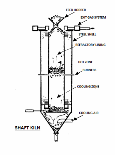
Figure 2
|